- 產品與解決方案
- 行業解決方案
- 服務
- 支持
- 合作夥伴
- 關於我們


12-GRE配置
本章節下載: 12-GRE配置 (280.17 KB)
目 錄
GRE(Generic Routing Encapsulation,通用路由封裝)協議是對某些網絡層協議(如IP和IPX)的數據報文進行封裝,使這些被封裝的數據報文能夠在另一個網絡層協議(如IP)中傳輸。封裝後的數據報文在網絡中傳輸的路徑,稱為GRE隧道。GRE隧道是一個虛擬的點到點的連接,GRE隧道的兩端分別對數據報進行封裝及解封裝。
圖1-1 GRE封裝後的報文格式
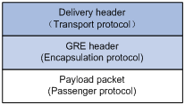
如圖1-1所示,GRE封裝後的報文包括如下幾個部分:
l 淨荷數據(Payload packet):需要封裝和傳輸的數據報文。淨荷數據的協議類型,稱為乘客協議(Passenger Protocol)。
l GRE頭(GRE header):係統收到淨荷數據後,在淨荷數據上添加GRE頭,使其成為GRE報文。對淨荷數據進行封裝的GRE協議,稱為封裝協議(Encapsulation Protocol)。
l 傳輸協議的報文頭(Delivery header):負責轉發封裝後報文的網絡協議,稱為傳輸協議(Delivery Protocol或者Transport Protocol)。在GRE報文上需要增加傳輸協議的報文頭,以便傳輸協議對封裝後的報文進行轉發處理。
圖1-2 GRE封裝報文舉例
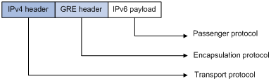
IPv6報文通過GRE隧道穿越IPv4網絡時,報文格式如圖1-2所示。其中,乘客協議為IPv6,封裝協議為GRE,傳輸協議為IPv4。
根據傳輸協議的不同,GRE隧道可以分為:
l GRE over IPv4:傳輸協議為IPv4,乘客協議為任意網絡層協議。
l GRE over IPv6:傳輸協議為IPv6,乘客協議為任意網絡層協議。
圖1-3 X協議網絡通過GRE隧道互連
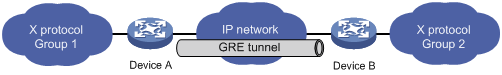
下麵以圖1-3的網絡為例說明X協議的報文穿越IP網絡在GRE隧道中傳輸的過程:
l Device A連接Group 1的接口收到X協議報文後,首先交由X協議處理;
l X協議檢查報文頭中的目的地址域來確定如何路由此包;
l 若報文的目的地址要經過Tunnel才能到達,則設備將此報文發給相應的Tunnel接口;
l Tunnel接口收到此報文後進行GRE封裝,再封裝IP報文頭後,設備根據此IP包的目的地址及路由表對報文進行轉發,從相應的網絡接口發送出去。
![]()
對於無線PoE注入器,封裝後的報文不能根據目的地址和路由表進行第二次三層轉發,需要將封裝後的報文發送給業務環回口,由業務環回口將報文回送給轉發模塊後,再進行三層轉發。
解封裝過程和加封裝的過程相反。
l Device B從Tunnel接口收到IP報文,檢查目的地址;
l 如果目的地是本路由器,且IP報文頭中的協議號為47(表示封裝的報文為GRE報文),則Device B剝掉此報文的IP報頭,交給GRE協議處理(進行檢驗密鑰、檢查校驗和及報文的序列號等);
l GRE協議完成相應的處理後,剝掉GRE報頭,再交由X協議對此數據報進行後續的轉發處理。
![]()
GRE收發雙方的加封裝、解封裝處理,以及由於封裝造成的數據量增加,會導致使用GRE後設備的數據轉發效率有一定程度的下降。
與GRE相關的協議規範有:
l RFC 1701:Generic Routing Encapsulation (GRE)
l RFC 1702:Generic Routing Encapsulation over IPv4 networks
l RFC 2784:Generic Routing Encapsulation (GRE)
l 設備上存在已經配置IP地址、能夠進行正常通訊的接口(如VLAN接口,Loopback接口等),該接口將作為Tunnel接口的源接口。
l 配置GRE over IPv4隧道前,需要先創建業務類型為Tunnel的業務環回組,並將設備上未使用的二層以太網接口加入該業務環回組。關於業務環回組的詳細介紹,請參見“二層技術-以太網交換配置指導”中的“業務環回組”。
|
操作 |
命令 |
說明 |
|
進入係統視圖 |
system-view |
- |
|
創建一個Tunnel接口,並進入該Tunnel接口視圖 |
interface tunnel interface-number |
必選 缺省情況下,設備上無Tunnel接口 |
|
設置Tunnel接口的IPv4地址 |
ip address ip-address { mask | mask-length } |
必選 缺省情況下,Tunnel接口上沒有設置IPv4地址 |
|
配置隧道模式為GRE over IPv4 |
tunnel-protocol gre |
可選 缺省情況下,采用GRE over IPv4隧道模式 在隧道的兩端應配置相同的隧道模式,否則可能造成報文傳輸失敗 |
|
設置Tunnel接口的源端地址或接口 |
source { ip-address | interface-type interface-number } |
必選 缺省情況下,Tunnel接口上沒有設置源端地址和接口 |
|
設置Tunnel接口的目的端地址 |
destination ip-address |
必選 缺省情況下,Tunnel接口上沒有設置目的端地址 |
|
配置通過Tunnel轉發報文的路由 |
配置的詳細情況請參見“三層技術-IP路由配置指導”中的“靜態路由”或其他路由協議配置 |
必選 在源端路由器和目的端路由器上都必須存在經過Tunnel轉發報文的路由,這樣需要進行GRE封裝的報文才能正確轉發。可以配置靜態路由,也可以配置動態路由 |
|
退回係統視圖 |
quit |
- |
|
配置丟棄含有IPv4兼容IPv6地址的IPv6報文 |
tunnel discard ipv4-compatible-packet |
可選 缺省情況下,不會丟棄含有IPv4兼容IPv6地址的IPv6報文 |
![]()
l Tunnel接口的詳細介紹,及Tunnel接口下的更多配置命令,請參見“三層技術-IP業務配置指導”中的“隧道”。
l interface tunnel、tunnel-protocol、source、destination和tunnel discard ipv4-compatible-packet命令的詳細介紹,請參見“三層技術-IP業務命令參考”中的“隧道”。
![]()
l Tunnel的源端地址與目的端地址唯一標識了一個通道。Tunnel兩端必須配置源端地址與目的端地址,且兩端地址互為源地址和目的地址。
l 兩個或兩個以上使用同種封裝協議的Tunnel接口不能配置完全相同的源地址和目的地址。
l 配置Tunnel接口的源端地址時,若采用配置源接口形式,則Tunnel的源地址取的是源接口的主IP地址。
l 配置通過Tunnel轉發的路由時,可以手工配置一條靜態路由,目的地址是未進行GRE封裝的報文的目的地址,下一跳是對端Tunnel接口的地址。也可以在Tunnel接口上和與私網相連的路由器接口上分別使能動態路由協議,由動態路由協議來建立通過Tunnel轉發的路由表項。
l 在Tunnel接口配置的靜態路由的目的地址不能與Tunnel接口的地址在同一網段。
l 設備上存在已經配置IP地址、能夠進行正常通訊的接口(如VLAN接口,Loopback接口等),該接口將作為Tunnel接口的源接口。
l 配置GRE over IPv6隧道前,需要先創建業務類型為Tunnel的業務環回組,並將設備上未使用的二層以太網接口加入該業務環回組。關於業務環回組的詳細介紹,請參見“二層技術-以太網交換配置指導”中的“業務環回組”。
|
操作 |
命令 |
說明 |
|
進入係統視圖 |
system-view |
- |
|
使能IPv6報文轉發功能 |
ipv6 |
必選 缺省情況下,關閉IPv6報文轉發功能 |
|
創建一個Tunnel接口,並進入該Tunnel接口視圖 |
interface tunnel interface-number |
必選 缺省情況下,設備上無Tunnel接口 |
|
設置Tunnel接口的IPv4地址 |
ip address ip-address { mask | mask-length } |
必選 缺省情況下,Tunnel接口上沒有設置IPv4地址 |
|
配置隧道模式為GRE over IPv6 |
tunnel-protocol gre ipv6 |
必選 缺省情況下,采用GRE over IPv4隧道模式 在隧道的兩端應配置相同的隧道模式,否則可能造成報文傳輸失敗 |
|
設置Tunnel接口的源端地址或接口 |
source { ipv6-address | interface-type interface-number } |
必選 缺省情況下,Tunnel接口上沒有設置源端地址和接口 |
|
設置Tunnel接口的目的端地址 |
destination ipv6-address |
必選 缺省情況下,Tunnel接口上沒有設置目的端地址 |
|
退回係統視圖 |
quit |
- |
|
配置丟棄含有IPv4兼容IPv6地址的IPv6報文 |
tunnel discard ipv4-compatible-packet |
可選 缺省情況下,不會丟棄含有IPv4兼容IPv6地址的IPv6報文 |
|
配置通過Tunnel轉發報文的路由 |
配置的詳細情況請參見“三層技術-IP路由配置指導”中的“靜態路由”或其他路由協議配置 |
必選 在源端路由器和目的端路由器上都必須存在經過Tunnel轉發報文的路由,這樣需要進行GRE封裝的報文才能正確轉發。可以配置靜態路由,也可以配置動態路由 |
![]()
l interface tunnel、tunnel-protocol、source、destination和tunnel discard ipv4-compatible-packet命令的詳細介紹,請參見“三層技術-IP業務命令參考”中的“隧道”。
l Tunnel接口的詳細介紹,及Tunnel接口下的更多配置命令,請參見“三層技術-IP業務配置指導”中的“隧道”。
![]()
l 以上各項Tunnel接口下進行的功能特性配置,在刪除Tunnel接口後,該接口上的所有配置也將被刪除。
l Tunnel的源端地址與目的端地址唯一標識了一個通道。Tunnel兩端必須配置源端地址與目的端地址,且兩端地址互為源地址和目的地址。
l 兩個或兩個以上使用同種封裝協議的Tunnel接口不能配置完全相同的源地址和目的地址。
l 配置Tunnel接口的源端地址時,若采用配置源接口形式,則Tunnel的源地址取的是源接口的主IP地址。
l 配置通過Tunnel轉發的路由時,可以手工配置一條靜態路由,目的地址是未進行GRE封裝的報文的目的地址,下一跳是對端Tunnel接口的地址。也可以在Tunnel接口上和與私網相連的路由器接口上分別使能動態路由協議,由動態路由協議來建立通過Tunnel轉發的路由表項。
l 在Tunnel接口配置的靜態路由的目的地址不能與Tunnel接口的地址在同一網段。
在完成上述配置後,在任意視圖下執行display命令可以顯示配置後GRE的運行情況,通過查看顯示信息驗證配置的效果。
表1-3 GRE的顯示和維護
|
操作 |
命令 |
|
顯示Tunnel接口的相關信息 |
display interface [ tunnel ] [ brief [ down ] ] [ | { begin | exclude | include } regular-expression ] display interface tunnel number [ brief ] [ | { begin | exclude | include } regular-expression ] |
|
顯示Tunnel接口的IPv6相關信息 |
display ipv6 interface tunnel [ number ] [ brief ] [ | { begin | exclude | include } regular-expression ] |
![]()
display interface tunnel和display ipv6 interface tunnel命令的詳細介紹,請參見“三層技術-IP業務命令參考”中的“隧道”。
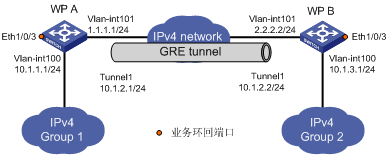
無線PoE注入器WP A和無線PoE注入器WP B之間通過Internet相連。運行IP協議的私有網絡的兩個子網Group 1和Group 2,通過在兩台無線PoE注入器之間使用GRE建立隧道實現互聯。
圖1-4 GRE over IPv4應用組網圖
![]()
在開始下麵的配置之前,需確保WP A和WP B之間路由可達。
(1) 配置無線PoE注入器WP A
# 配置接口Ethernet1/0/1。
<WPA> system-view
[WPA] vlan 100
[WPA-vlan100] port Ethernet 1/0/1
[WPA-vlan100] quit
[WPA] interface vlan-interface 100
[WPA-Vlan-interface100] ip address 10.1.1.1 255.255.255.0
[WPA-Vlan-interface100] quit
# 配置接口Ethernet1/0/2(隧道的實際物理接口)。
[WPA] vlan 101
[WPA-vlan101] port Ethernet 1/0/2
[WPA-vlan101] quit
[WPA] interface vlan-interface 101
[WPA-Vlan-interface101] ip address 1.1.1.1 255.255.255.0
[WPA-Vlan-interface101] quit
# 創建業務環回組1,並配置服務類型為tunnel。
[WPA] service-loopback group 1 type tunnel
# 將接口Ethernet1/0/3加入業務環回組1,並在該端口上關閉STP、NDP和LLDP功能。
[WPA] interface Ethernet 1/0/3
[WPA-Ethernet1/0/3] undo stp enable
[WPA-Ethernet1/0/3] undo ndp enable
[WPA-Ethernet1/0/3] undo lldp enable
[WPA-Ethernet1/0/3] port service-loopback group 1
[WPA-Ethernet1/0/3] quit
# 創建Tunnel1接口。
[WPA] interface tunnel 1
# 配置Tunnel1接口的IP地址。
[WPA-Tunnel1] ip address 10.1.2.1 255.255.255.0
# 配置Tunnel封裝模式為GRE over IPv4隧道模式。
[WPA-Tunnel1] tunnel-protocol gre
# 配置Tunnel1接口的源地址(Ethernet1/0/2所屬VLAN接口的IP地址)。
[WPA-Tunnel1] source vlan-interface 101
# 配置Tunnel1接口的目的地址(WP B的Ethernet1/0/2所屬VLAN接口的IP地址)。
[WPA-Tunnel1] destination 2.2.2.2
# 在Tunnel接口視圖下指定隧道引用業務環回組1。
[WPA-Tunnel1] service-loopback-group 1
[WPA-Tunnel1] quit
# 配置從WP A經過Tunnel1接口到Group 2的靜態路由。
[WPA] ip route-static 10.1.3.0 255.255.255.0 tunnel 1
(2) 配置無線PoE注入器WP B
# 配置接口Ethernet1/0/1。
<WPB> system-view
[WPB] vlan 100
[WPB-vlan100] port Ethernet 1/0/1
[WPB-vlan100] quit
[WPB] interface vlan-interface 100
[WPB-Vlan-interface100] ip address 10.1.3.1 255.255.255.0
[WPB-Vlan-interface100] quit
# 配置接口Ethernet1/0/2(隧道的實際物理接口)。
[WPB] vlan 101
[WPB-vlan101] port Ethernet 1/0/2
[WPB-vlan101] quit
[WPB] interface vlan-interface 101
[WPB-Vlan-interface101] ip address 2.2.2.2 255.255.255.0
[WPB-Vlan-interface101] quit
# 創建業務環回組1,並配置服務類型為tunnel。
[WPB] service-loopback group 1 type tunnel
# 將接口Ethernet1/0/3加入業務環回組1,並在該端口上關閉STP、NDP和LLDP功能。
[WPB] interface Ethernet 1/0/3
[WPB-Ethernet1/0/3] undo stp enable
[WPB-Ethernet1/0/3] undo ndp enable
[WPB-Ethernet1/0/3] undo lldp enable
[WPB-Ethernet1/0/3] port service-loopback group 1
[WPB-Ethernet1/0/3] quit
# 創建Tunnel1接口。
[WPB] interface tunnel 1
# 配置Tunnel1接口的IP地址。
[WPB-Tunnel1] ip address 10.1.2.2 255.255.255.0
# 配置Tunnel封裝模式為GRE over IPv4隧道模式。
[WPB-Tunnel1] tunnel-protocol gre
# 配置Tunnel1接口的源地址(Ethernet1/0/2所屬VLAN接口的IP地址)。
[WPB-Tunnel1] source vlan-interface 101
# 配置Tunnel1接口的目的地址(WP A的Ethernet1/0/2所屬VLAN接口的IP地址)。
[WPB-Tunnel1] destination 1.1.1.1
# 在Tunnel接口視圖下指定隧道引用業務環回組1。
[WPB-Tunnel1] service-loopback-group 1
[WPB-Tunnel1] quit
# 配置從WP B經過Tunnel1接口到Group 1的靜態路由。
[WPB] ip route-static 10.1.1.0 255.255.255.0 Tunnel 1
(3) 驗證配置結果
# 完成以上配置後,分別查看WP A和WP B的Tunnel接口狀態。
[WPA] display interface tunnel 1
Tunnel1 current state: UP
Line protocol current state: UP
Description: Tunnel1 Interface
The Maximum Transmit Unit is 1476
Internet Address is 10.1.2.1/24 Primary
Encapsulation is TUNNEL, service-loopback-group ID is 1.
Tunnel source 1.1.1.1, destination 2.2.2.2
Tunnel bandwidth 64 (kbps)
Tunnel protocol/transport GRE/IP
GRE key disabled
Checksumming of GRE packets disabled
Last clearing of counters: Never
Last 300 seconds input: 0 bytes/sec, 0 packets/sec
Last 300 seconds output: 0 bytes/sec, 0 packets/sec
10 packets input, 840 bytes
0 input error
10 packets output, 840 bytes
0 output error
[WPB] display interface tunnel 1
Tunnel1 current state: UP
Line protocol current state: UP
Description: Tunnel1 Interface
The Maximum Transmit Unit is 1476
Internet Address is 10.1.2.2/24 Primary
Encapsulation is TUNNEL, service-loopback-group ID is 1.
Tunnel source 2.2.2.2, destination 1.1.1.1
Tunnel bandwidth 64 (kbps)
Tunnel protocol/transport GRE/IP
GRE key disabled
Checksumming of GRE packets disabled
Last clearing of counters: Never
Last 300 seconds input: 2 bytes/sec, 0 packets/sec
Last 300 seconds output: 2 bytes/sec, 0 packets/sec
10 packets input, 840 bytes
0 input error
10 packets output, 840 bytes
0 output error
# 從WP B可以Ping通WP A上VLAN接口100的地址。
[WPB] ping 10.1.1.1
PING 10.1.1.1: 56 data bytes, press CTRL_C to break
Reply from 10.1.1.1: bytes=56 Sequence=1 ttl=255 time=2 ms
Reply from 10.1.1.1: bytes=56 Sequence=2 ttl=255 time=2 ms
Reply from 10.1.1.1: bytes=56 Sequence=3 ttl=255 time=2 ms
Reply from 10.1.1.1: bytes=56 Sequence=4 ttl=255 time=2 ms
Reply from 10.1.1.1: bytes=56 Sequence=5 ttl=255 time=2 ms
--- 10.1.1.1 ping statistics ---
5 packet(s) transmitted
5 packet(s) received
0.00% packet loss
round-trip min/avg/max = 2/2/2 ms
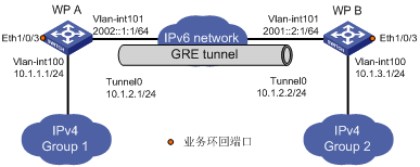
運行IP協議的兩個子網Group1和Group2通過IPv6網絡相連。通過在無線PoE注入器WPA和無線PoE注入器WPB之間建立GRE over IPv6隧道,實現兩個子網穿越IPv6網絡互聯。
圖1-5 GRE over IPv6應用組網圖
![]()
在開始下麵的配置之前,需確保WP A和WP B之間路由可達。
(1) 配置無線PoE注入器WP A
<WPA> system-view
# 使能IPv6。
[WPA] ipv6
# 配置接口Vlan-interface100。
[WPA] vlan 100
[WPA-vlan100] port Ethernet 1/0/1
[WPA-vlan100] quit
[WPA] interface vlan-interface 100
[WPA-Vlan-interface100] ip address 10.1.1.1 255.255.255.0
[WPA-Vlan-interface100] quit
# 配置接口Vlan-interface101(隧道的實際物理接口)。
[WPA] vlan 101
[WPA-vlan101] port Ethernet 1/0/2
[WPA-vlan101] quit
[WPA] interface vlan-interface 101
[WPA-Vlan-interface101] ipv6 address 2002::1:1 64
[WPA-Vlan-interface101] quit
# 創建業務環回組1,並配置服務類型為tunnel。
[WPA] service-loopback group 1 type tunnel
# 將接口Ethernet1/0/3加入業務環回組1,並在該端口上關閉STP、NDP和LLDP功能。
[WPA] interface Ethernet 1/0/3
[WPA-Ethernet1/0/3] undo stp enable
[WPA-Ethernet1/0/3] undo ndp enable
[WPA-Ethernet1/0/3] undo lldp enable
[WPA-Ethernet1/0/3] port service-loopback group 1
[WPA-Ethernet1/0/3] quit
# 創建Tunnel0接口。
[WPA] interface tunnel 0
# 配置Tunnel0接口的IP地址。
[WPA-Tunnel0] ip address 10.1.2.1 255.255.255.0
# 配置Tunnel封裝模式為GRE over IPv6隧道模式。
[WPA-Tunnel0] tunnel-protocol gre ipv6
# 配置Tunnel0接口的源地址(Vlan-interface101的IP地址)。
[WPA-Tunnel0] source 2002::1:1
# 配置Tunnel0接口的目的地址(WP B的Vlan-interface101的IP地址)。
[WPA-Tunnel0] destination 2001::2:1
# 在Tunnel接口視圖下指定隧道引用業務環回組1。
[WPA-Tunnel0] service-loopback-group 1
[WPA-Tunnel0] quit
# 配置從WP A經過Tunnel1接口到Group 2的靜態路由。
[WPA] ip route-static 10.1.3.0 255.255.255.0 tunnel 0
(2) 配置無線PoE注入器WP B
<WPB> system-view
# 使能IPv6。
[WPB] ipv6
# 配置接口Vlan-interface100。
[WPB] vlan 100
[WPB-vlan100] port Ethernet 1/0/1
[WPB-vlan100] quit
[WPB] interface vlan-interface 100
[WPB-Vlan-interface100] ip address 10.1.3.1 255.255.255.0
[WPB-Vlan-interface100] quit
# 配置接口Vlan-interface101(隧道的實際物理接口)。
[WPB] vlan 101
[WPB-vlan101] port Ethernet 1/0/2
[WPB-vlan101] quit
[WPB] interface vlan-interface 101
[WPB-Vlan-interface101] ipv6 address 2001::2:1 64
[WPB-Vlan-interface101] quit
# 創建業務環回組1,並配置服務類型為tunnel。
[WPB] service-loopback group 1 type tunnel
# 將接口Ethernet1/0/3加入業務環回組1,並在該端口上關閉STP、NDP和LLDP功能。
[WPB] interface Ethernet 1/0/3
[WPB-Ethernet1/0/3] undo stp enable
[WPB-Ethernet1/0/3] undo ndp enable
[WPB-Ethernet1/0/3] undo lldp enable
[WPB-Ethernet1/0/3] port service-loopback group 1
[WPB-Ethernet1/0/3] quit
# 創建Tunnel0接口。
[WPB] interface tunnel 0
# 配置Tunnel0接口的IP地址。
[WPB-Tunnel0] ip address 10.1.2.2 255.255.255.0
# 配置Tunnel封裝模式為GRE over IPv6隧道模式。
[WPB-Tunnel0] tunnel-protocol gre ipv6
# 配置Tunnel0接口的源地址(Vlan-interface101的IP地址)。
[WPB-Tunnel0] source 2001::2:1
# 配置Tunnel0接口的目的地址(WP A的Vlan-interface101的IP地址)。
[WPB-Tunnel0] destination 2002::1:1
# 在Tunnel接口視圖下指定隧道引用業務環回組1。
[WPB-Tunnel0] service-loopback-group 1
[WPB-Tunnel0] quit
# 配置從WP B經過Tunnel2接口到Group 1的靜態路由。
[WPB] ip route-static 10.1.1.0 255.255.255.0 tunnel 0
(3) 驗證配置結果
# 完成以上配置後,分別查看WP A和WP B的Tunnel接口狀態。
[WPA] display interface Tunnel 0
Tunnel0 current state: UP
Line protocol current state: UP
Description: Tunnel0 Interface
The Maximum Transmit Unit is 1456
Internet Address is 10.1.2.1/24 Primary
Encapsulation is TUNNEL, service-loopback-group ID is 1.
Tunnel source 2002::1:1, destination 2001::2:1
Tunnel protocol/transport GRE/IPv6
GRE key disabled
Checksumming of GRE packets disabled
Last clearing of counters: Never
Last 300 seconds input: 0 bytes/sec, 0 packets/sec
Last 300 seconds output: 0 bytes/sec, 0 packets/sec
10 packets input, 840 bytes
0 input error
10 packets output, 840 bytes
0 output error
[WPB] display interface Tunnel 0
Tunnel0 current state: UP
Line protocol current state: UP
Description: Tunnel0 Interface
The Maximum Transmit Unit is 1456
Internet Address is 10.1.2.2/24 Primary
Encapsulation is TUNNEL, service-loopback-group ID is 1.
Tunnel source 2001::2:1, destination 2002::1:1
Tunnel protocol/transport GRE/IPv6
GRE key disabled
Checksumming of GRE packets disabled
Last clearing of counters: Never
Last 300 seconds input: 0 bytes/sec, 0 packets/sec
Last 300 seconds output: 0 bytes/sec, 0 packets/sec
10 packets input, 840 bytes
0 input error
10 packets output, 840 bytes
0 output error
# 從WP B可以Ping通WP A上VLAN接口100的地址。
[WPB] ping 10.1.1.1
PING 10.1.1.1: 56 data bytes, press CTRL_C to break
Reply from 10.1.1.1: bytes=56 Sequence=1 ttl=255 time=3 ms
Reply from 10.1.1.1: bytes=56 Sequence=2 ttl=255 time=2 ms
Reply from 10.1.1.1: bytes=56 Sequence=3 ttl=255 time=2 ms
Reply from 10.1.1.1: bytes=56 Sequence=4 ttl=255 time=2 ms
Reply from 10.1.1.1: bytes=56 Sequence=5 ttl=255 time=3 ms
--- 10.1.1.1 ping statistics ---
5 packet(s) transmitted
5 packet(s) received
0.00% packet loss
round-trip min/avg/max = 2/2/3 ms
GRE的配置相對比較簡單,但要注意配置的一致性,大部分的錯誤都可以通過使用調試命令debugging gre和debugging tunnel定位。這裏僅就一種錯誤進行分析,如圖1-6所示。
圖1-6 GRE排錯示例
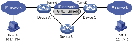
故障之一:Tunnel兩端接口配置正確且Tunnel兩端可以ping通,但Host A和Host B之間卻無法ping通。
故障排除:可以按照如下步驟進行。
l 在任意視圖下,在Device A和Device C分別執行display ip routing-table命令,觀察在Device A是否有經過Tunnel0接口到10.2.0.0/16的路由;在Device C是否有經過Tunnel0接口到10.1.0.0/16的路由。
l 如果在上一步的輸出中發現缺少相應的靜態路由,在係統視圖下使用ip route-static命令添加。以Device A為例,配置如下:
[DeviceA] ip route-static 10.2.0.0 255.255.0.0 tunnel 0
不同款型規格的資料略有差異, 詳細信息請向具體銷售和400谘詢。H3C保留在沒有任何通知或提示的情況下對資料內容進行修改的權利!


